Key Technical Specifications
| Parameter Name | Parameter Value |
|---|---|
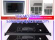
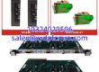
| Product Model | 3500/25 149369-01 |
| Manufacturer | Bently Nevada |
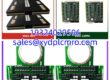
| Product Type | Enhanced Keyphasor Module |
| Channel Capacity | Dual Channel (2 Inputs / 2 Outputs) |
| Physical Size | Half-Height Module |
| Power Consumption | 3.2 Watts (Typical) |
| Sensor Power Supply | -24 Vdc, 40 mA max per channel |
| Buffered Output Impedance | 504 Ω max |
| Operating Temperature | -30°C to +65°C (Non-Barrier I/O) |
| Input Signal Range | +0.8V to -21.0V (Non-isolated) |
| Front Panel Indicators | OK LED, TX/RX LED |
| System Compatibility | 3500 Framework / System 1 Software |
Product Introduction
If you have ever tried to balance a massive turbine rotor without a clean reference pulse, you know that garbage timing data equals wasted hours on the machine deck. The BENTLY 3500/25 149369-01 is the Enhanced Keyphasor module designed specifically to solve that problem. It acts as the heartbeat of the 3500 framework, taking raw, noisy analog pulses from proximity probes or magnetic pickups and converting them into crisp, digital timing markers.Engineers rely on this specific I/O module because it gives the monitoring cards the exact reference they need to calculate 1X amplitude and phase vectors. It handles up to 20 kHz of input frequency and supports multi-event-per-revolution inputs, which is critical for gearboxes. This specific 149369-01 revision completely replaces the older 125792-01 boards, and frankly, the signal processing upgrade is worth the swap. Just be careful with the isolated I/O versions if you are doing strict phase measurements, as they introduce a slight phase shift at high RPMs.
Quality SOP & Tech Pitfalls (The Reality Check)
Before we ship this module, it goes through a strict validation protocol. We start with a visual counterfeit check, ensuring the PWA board matches the 149369-01 spec. Next, it gets mounted in a live 3500 test rack where we verify the OK and TX/RX LEDs light up in the correct sequence. We use a Fluke 115 to check the -24Vdc sensor power output and ensure the 3.2W power draw is stable. Finally, we log the firmware revision and seal it in an anti-static bag.Now for the reality check: I once watched a tech spend an hour chasing a ghost vibration because he wired a passive magnetic pickup to a Keyphasor module expecting it to work at zero RPM. Passive magnetic pickups require the shaft to be spinning over 200 RPM just to generate enough voltage to trigger the module. Another common pitfall is ignoring the jumper settings on the back. If you are running TMR (Triple Modular Redundancy), you must install two of these modules in parallel. Failing to configure the primary and secondary Keyphasor inputs correctly will cause your voting logic to trip the machine during a routine startup.
Installation & Configuration Guide
- Pre-Installation: ⚠️ Safety First. Ensure the 3500 rack power is OFF and wait 60 seconds for capacitors to discharge. Take a clear photo of the existing Slot 1 module and the backplane DIP switches before touching anything.
- Removal: Label all Ethernet and USB cables. Press the top and bottom ejector tabs evenly and pull the old module straight out. Never pry it with a screwdriver, or you will bend the backplane pins.
- Installation: Copy DIP/Jumper settings exactly. This prevents 90% of startup communication failures. Align the 149369-01 I/O module with the Slot 1 guides and push firmly until the ejector tabs snap into place.
- Power-On & Testing: Restore 24V DC rack power. Watch the front panel: the OK LED should turn solid green within 30 seconds. Open System 1 software, verify the Ethernet link is active, and confirm that the CONFIG OK LED is illuminated before downloading any new parameters.
Compatible Replacement Models
| Replacement Model | Compatibility Tier | Field Notes |
|---|---|---|
| 3500/25-01-01-00 | ✅ Drop-in Replacement | The complete assembly part number for this exact Enhanced Keyphasor setup. |
| 149369-01 | ✅ Drop-in Replacement | This is the front panel component number; verify it matches your chassis. |
| 125792-01 | ❌ Hardware Mod Required | The legacy Keyphasor module. Completely replaced by 149369-01; do not buy this old revision. |
| 3500/25-02-01-00 | ⚠️ Software Compatible | Isolated I/O version. Requires verifying phase shift tolerances for your specific application. |
Frequently Asked Questions (FAQ)
Can I hot-swap this module if the rack is running?
No. While some 3500 modules support hot-swapping, pulling the Keyphasor while the rack is energized will drop the timing reference and can corrupt the backplane data bus. Always power down the rack first.Why is my OK LED blinking red?
That usually means the module has detected an internal fault or the sensor signal is out of range. Check your proximity probe gap and ensure the input signal is within the +0.8V to -21.0V range.Does this module handle the actual machine trip relays?
Not at all. The 3500/25 is strictly for timing and phase reference. Your 3500/32 or 3500/33 relay modules handle the safety trips independently. If this Keyphasor fails, your machine is still protected, but you will lose vector data.I need an isolated I/O module. Will this 149369-01 work?
No, the 149369-01 suffix specifically denotes the non-isolated version. If your plant requires isolation from the control system, you need to source the isolated I/O variant instead.Is the USB-B port on the front used for configuration?
Yes, but only for local, direct laptop connections during initial commissioning or troubleshooting. For continuous plant-wide monitoring, you should be using the RJ-45 Ethernet port connected to your plant network switch.Do I need a special license to capture transient waveforms?
You need the physical “Dynamic Data Enable Disk” (like the 3500/09 series) loaded into the System 1 software. Without that specific license key, the module will only collect standard steady-state data points.